Scia Design Forms Tools Pack
In this tutorial, you will learn how to activate the BIM-link between SCIA Engineer and IDEA StatiCa Concrete, how to import a whole structure and how to design it using IDEA StatiCa.
1 How to activate the link
- Download and install (as administrator) the latest version of IDEA StatiCa
- Make sure that you are using the supported version of SCIA Engineer
IDEA StatiCa automatically integrates the BIM link into your CAD/CAE software during its installation. You can check the status and activate more BIM links for later installed software in the BIM link installer.
Open IDEA StatiCa and navigate to the panel BIM and open the BIM link installer. A notification "Run as administrator" may appear, please confirm with the Yes button.
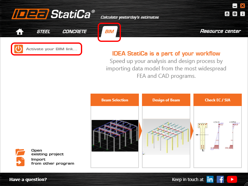
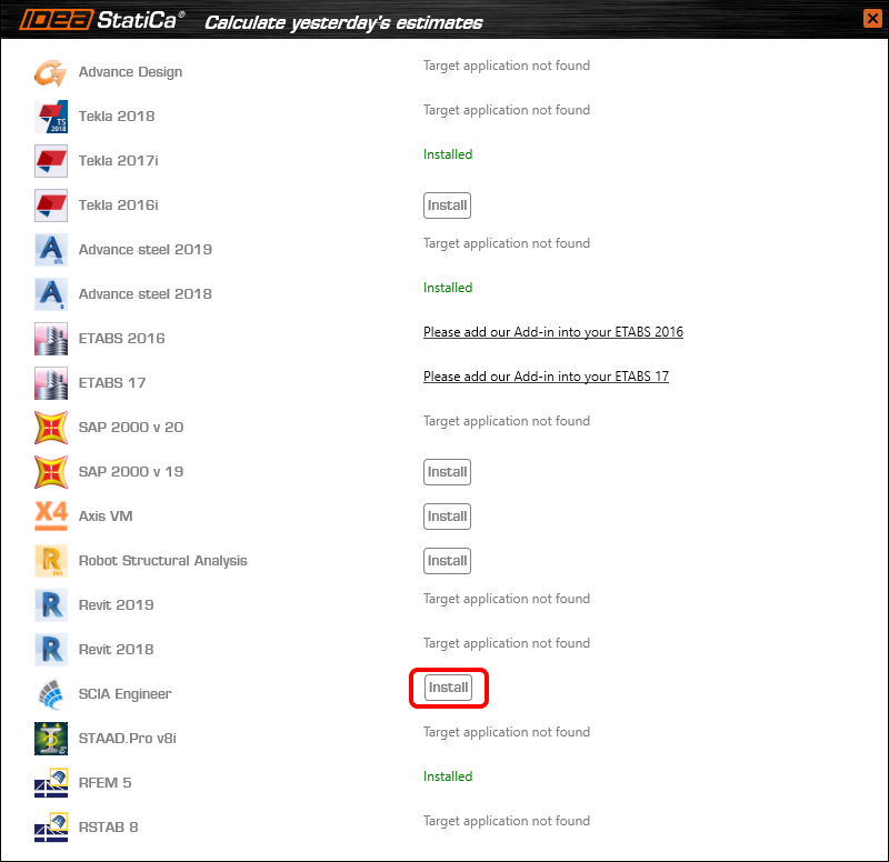
Select the software to integrate the IDEA StatiCa BIM link, click the Install button and check the Installed status.
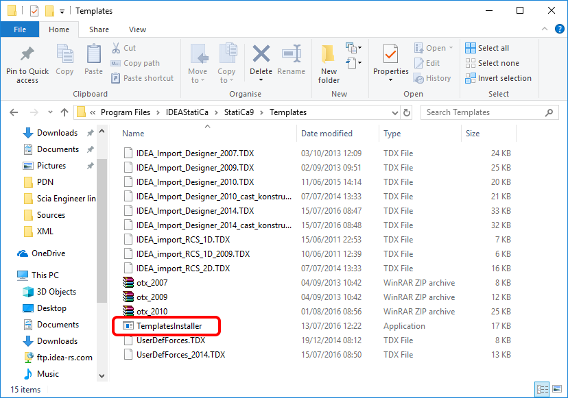
Before you import your first example, it is necessary to install the templates into Scia Engineer. To do that, you need to run TemplatesInstaller.exe usually to be found in the default installation folder of IDEA StatiCa (c:\Program Files\IDEAStatiCa\StatiCaX\Templates). There is no need to do this operation again if you do not change the SCIA Engineer version.
Select the version of SCIA Engineer to which the templates will be installed.
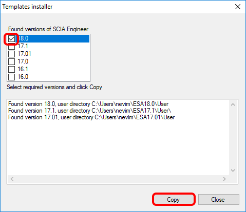
After Copy, you are ready for the export of the model.
2 Export
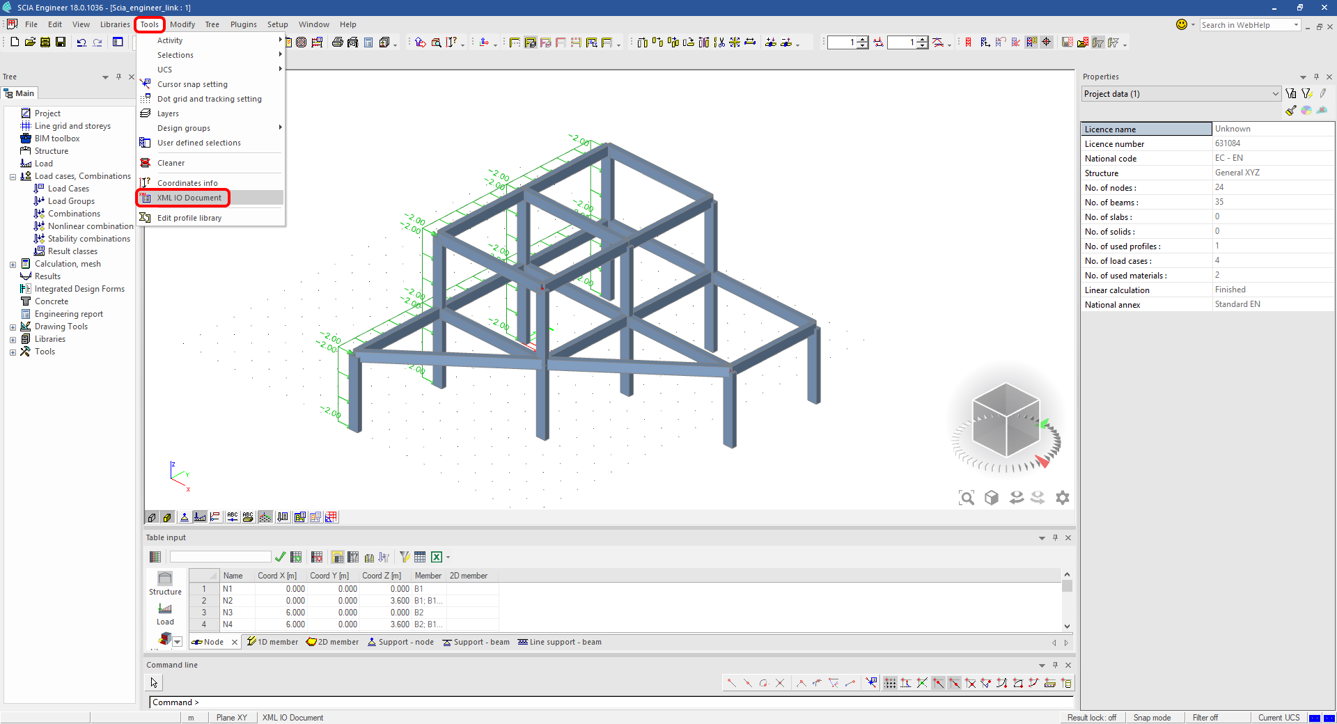
Open the model Scia_engineer_link.esa from downloaded source files, run linear analysis to obtain the results and in Tools menu select XML/IO document.
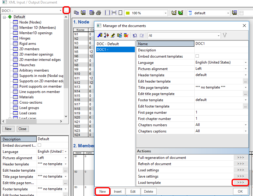
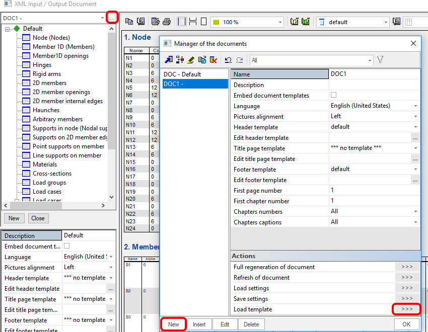
Create a new XML Input/Output document and load one of the installed templates.
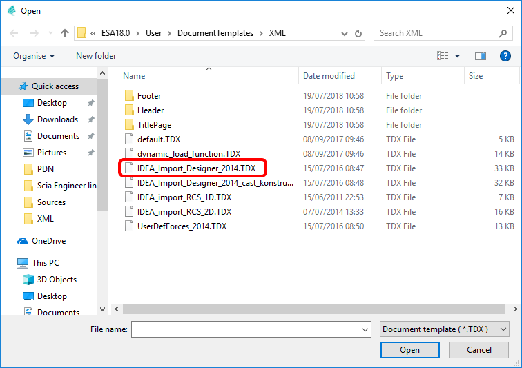
You export the whole structure in this example, so select the default highlighted template.
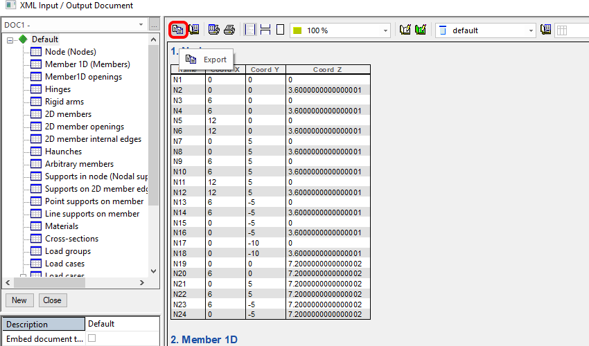
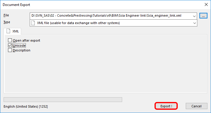
In the next dialog, set up the desired path to your XML and XML.DEF files. It is always important to keep both files in the same folder and with the same name (both keep necessary data for successful import).
3 Import
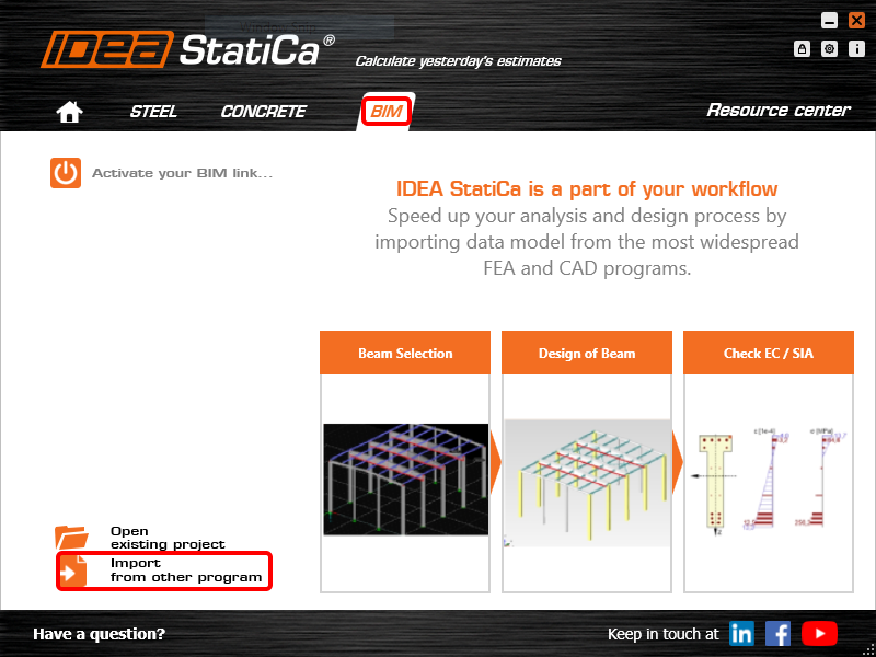
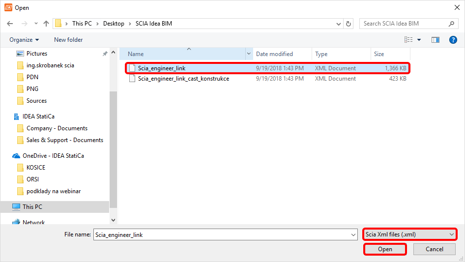
Open IDEA StatiCa and navigate to the panel BIM and click on SCIA Engineer. Select the exported XML file.
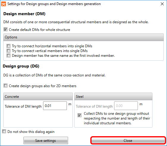
If you import for the first time, you need to set the generation of design groups and members.
The imported model looks like on the following picture. For a better view, you can turn on the rendering of all members as All solids. Also switch to design groups and select DG2 as you want to check all beams, highlighted in the main window, at the same time.
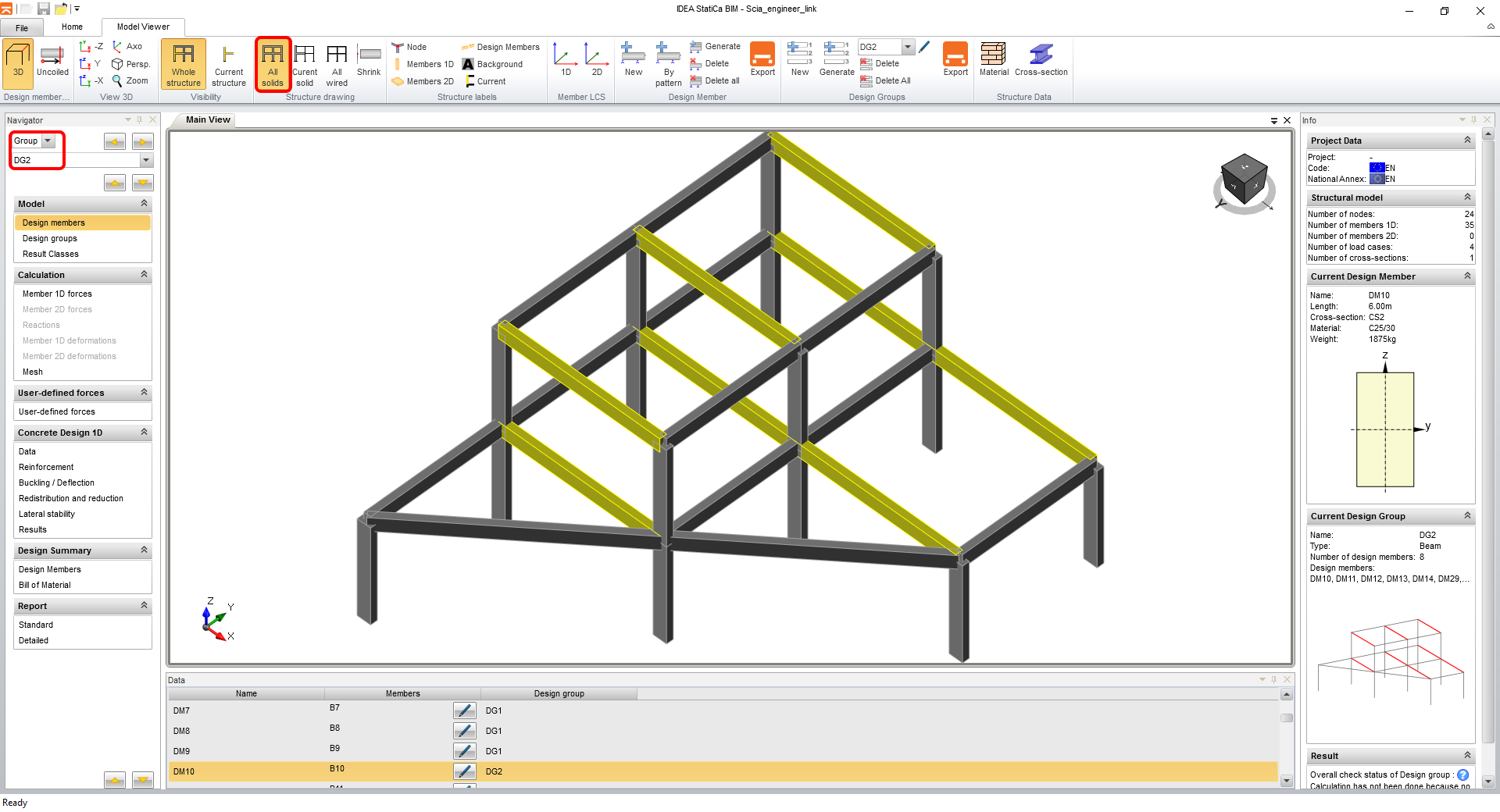
4 Design
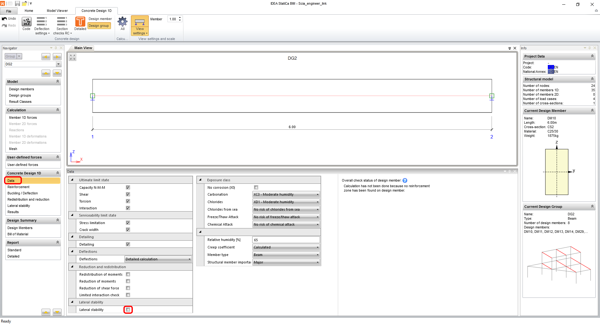
Go to the Data tab in the navigator to set all required types of checks and exposure classes. This type of example does not require the check of Lateral stability.
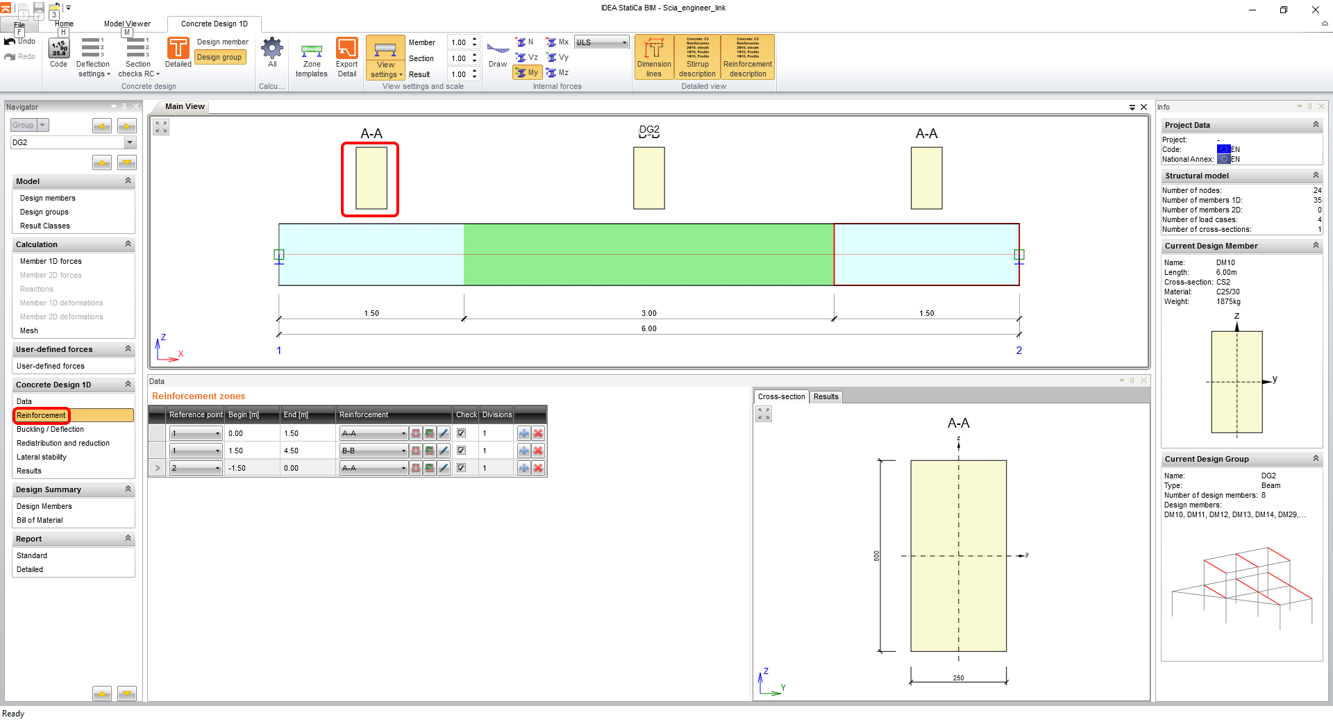
The next step is to input reinforcement. For the easiness of this tutorial, you will use generated zones of reinforcement. By clicking on the shape of the cross-section of zone A-A you open the reinforcement editor.
You will use the template for rectangular cross-sections, input the parameters and finish by clicking on OK.
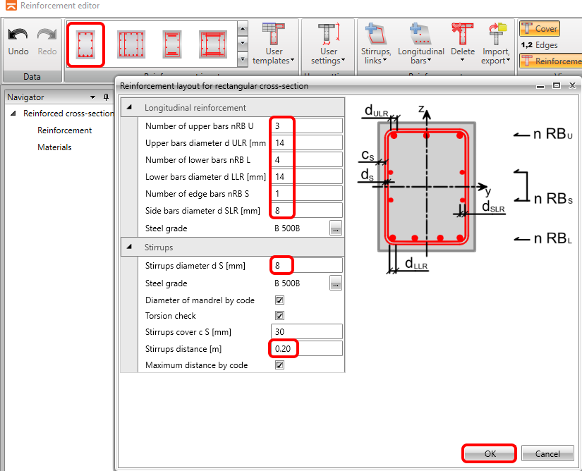
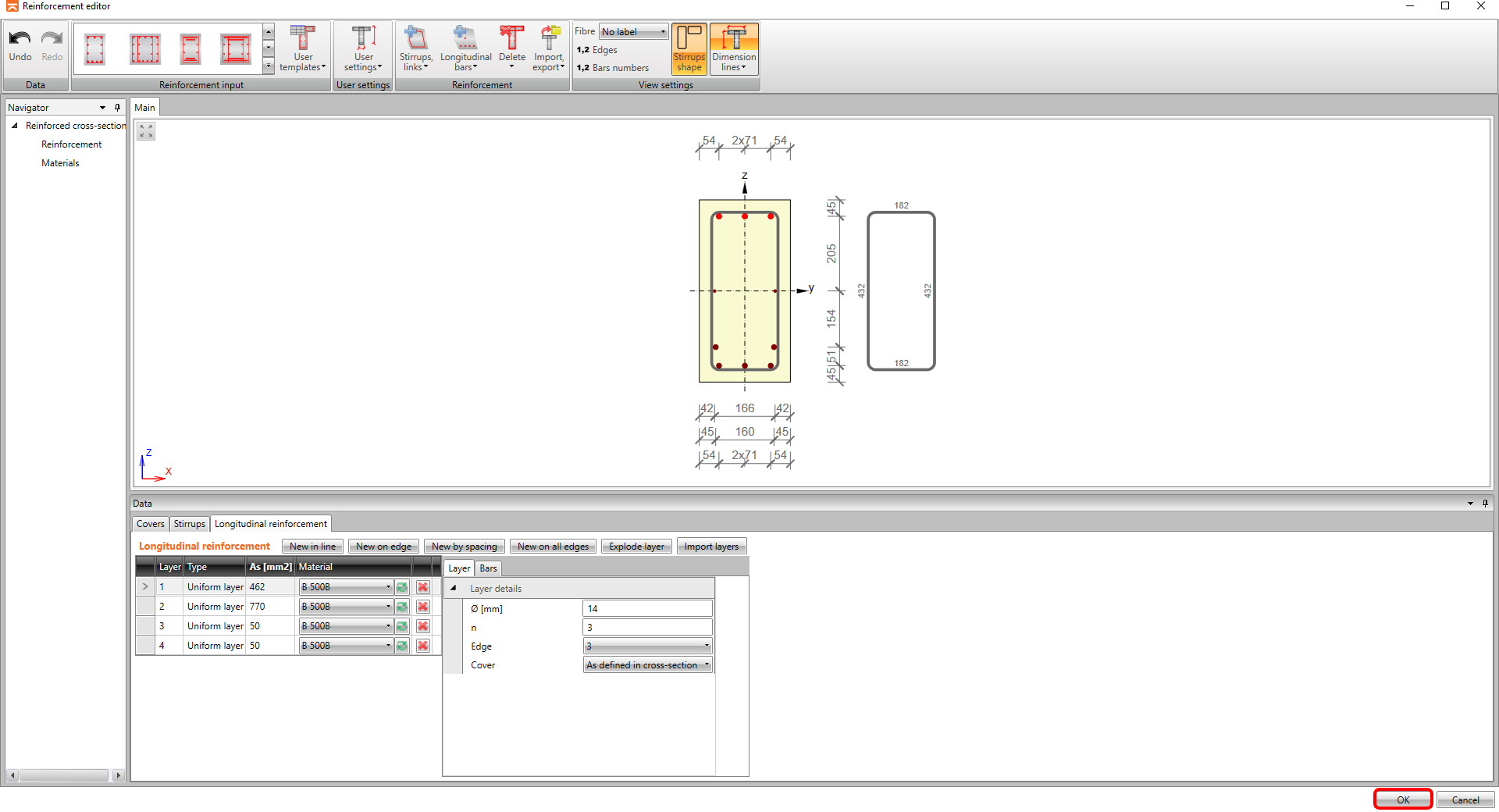
The reinforcement is showed in the scene according to the parameters (please note, that the software automatically distributed the reinforcement into two layers due to the detailing rules) and you can go back to beam application by clicking on OK.
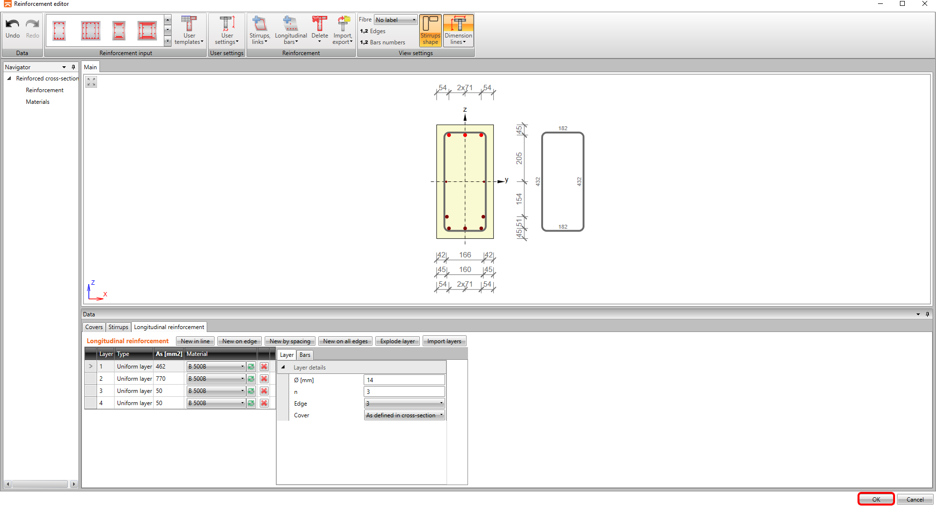
Continue with the reinforcing of zone B-B, again by clicking on the shape of cross-section.
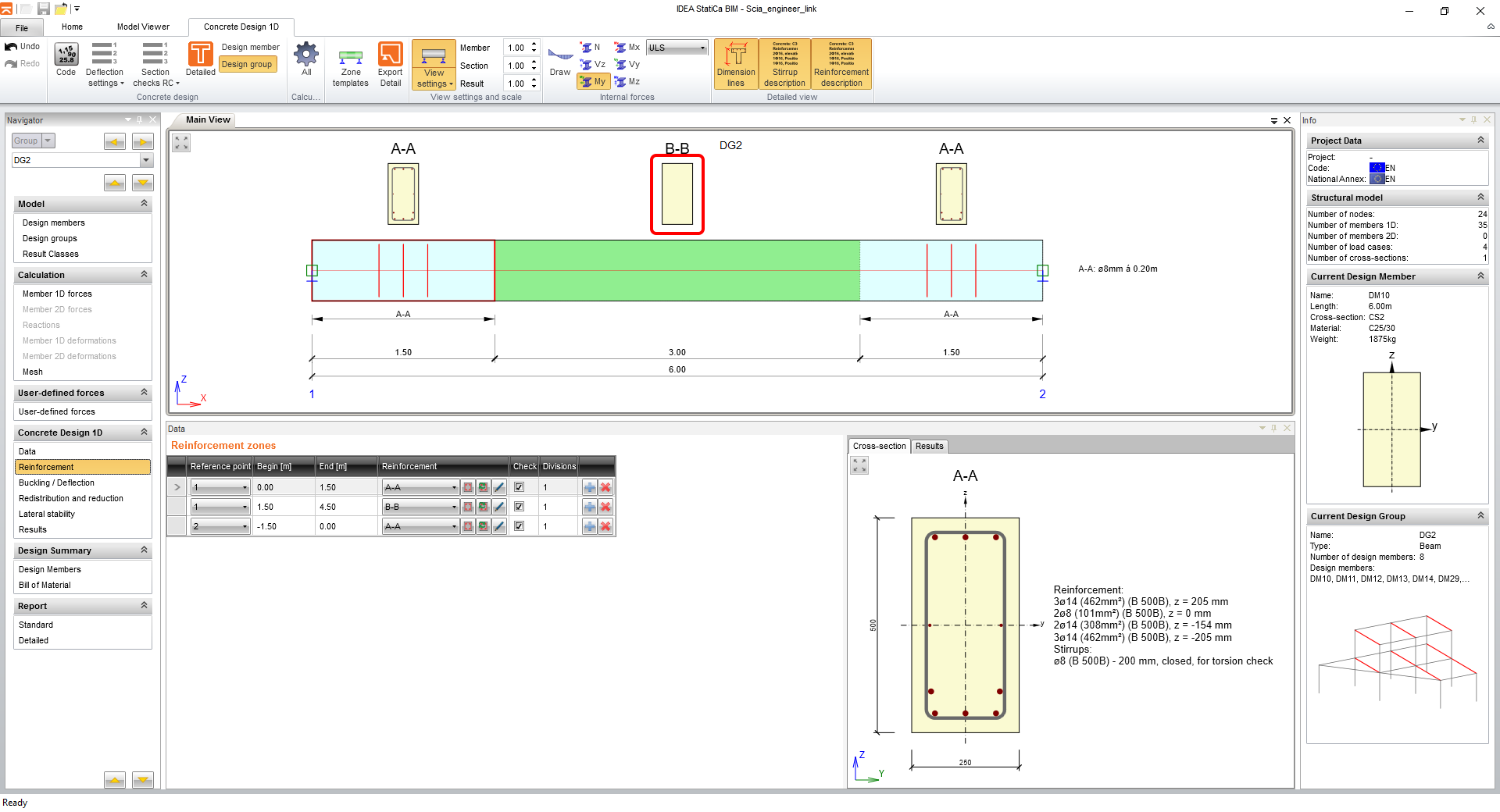
Repeat the steps for the reinforcement template.
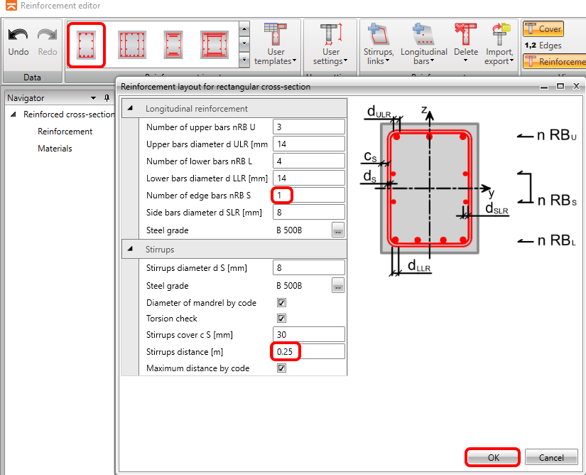
And the steps are finished by the OK button.
5 Check
Click on the Results tab and the calculations are performed automatically.
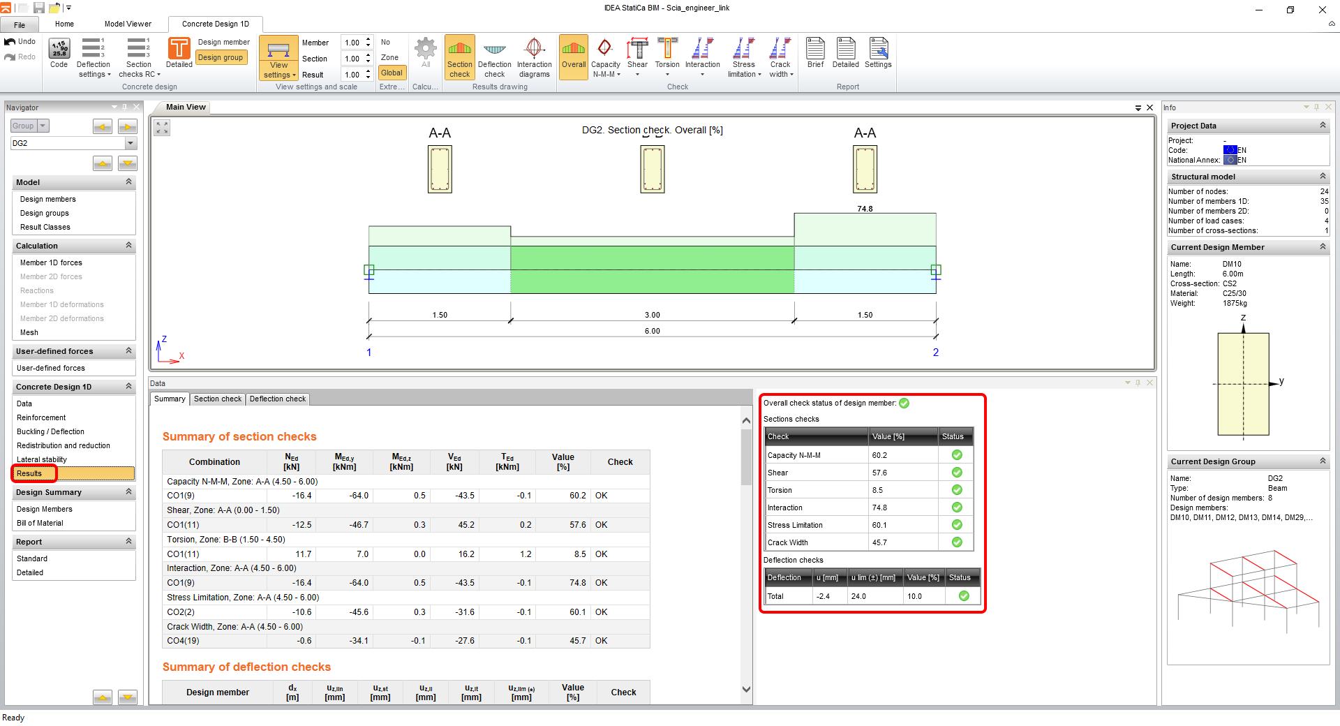
You can see on the right side of the screen, that the summary table shows all the checks as passing. You can always select the type of check to be shown in the scene by the ribbon icons.
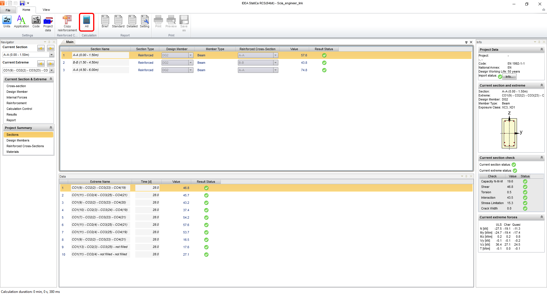
To see detailed results, you can export the sections to the RCS module by Detailed.

After the export, the RCS is opened in the Sections tab, where you run the calculation by All.
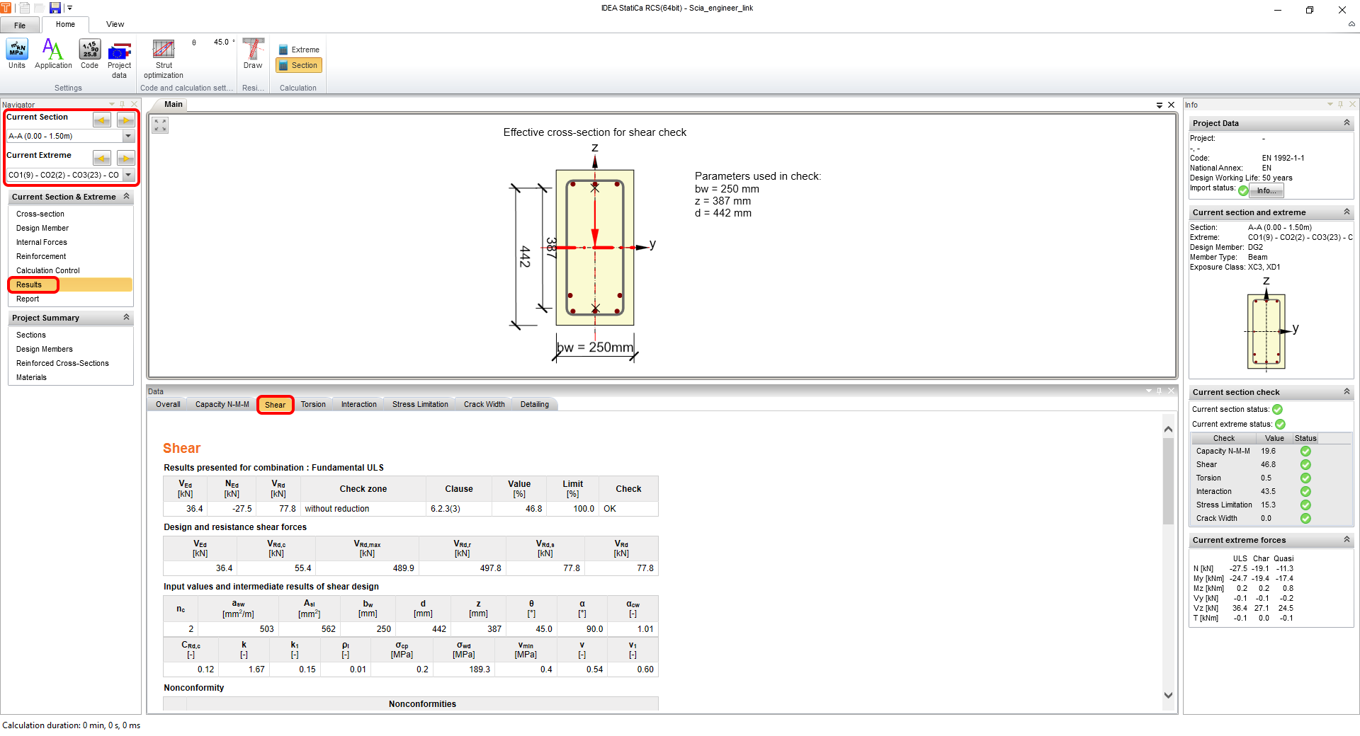
When you change the tab to Results you can go through all the checks and detailed results also in a visualized way together with all input/output parameters. On the left, in the navigator, you can switch between sections and extremes, for which you are plotting the results. Our screenshot shows the results of the first reinforcement zone A-A and Shear assessment results.
To close this review of results in RCS and to return to IDEA BIM, just click on the cross button in the right top corner.
6 Report
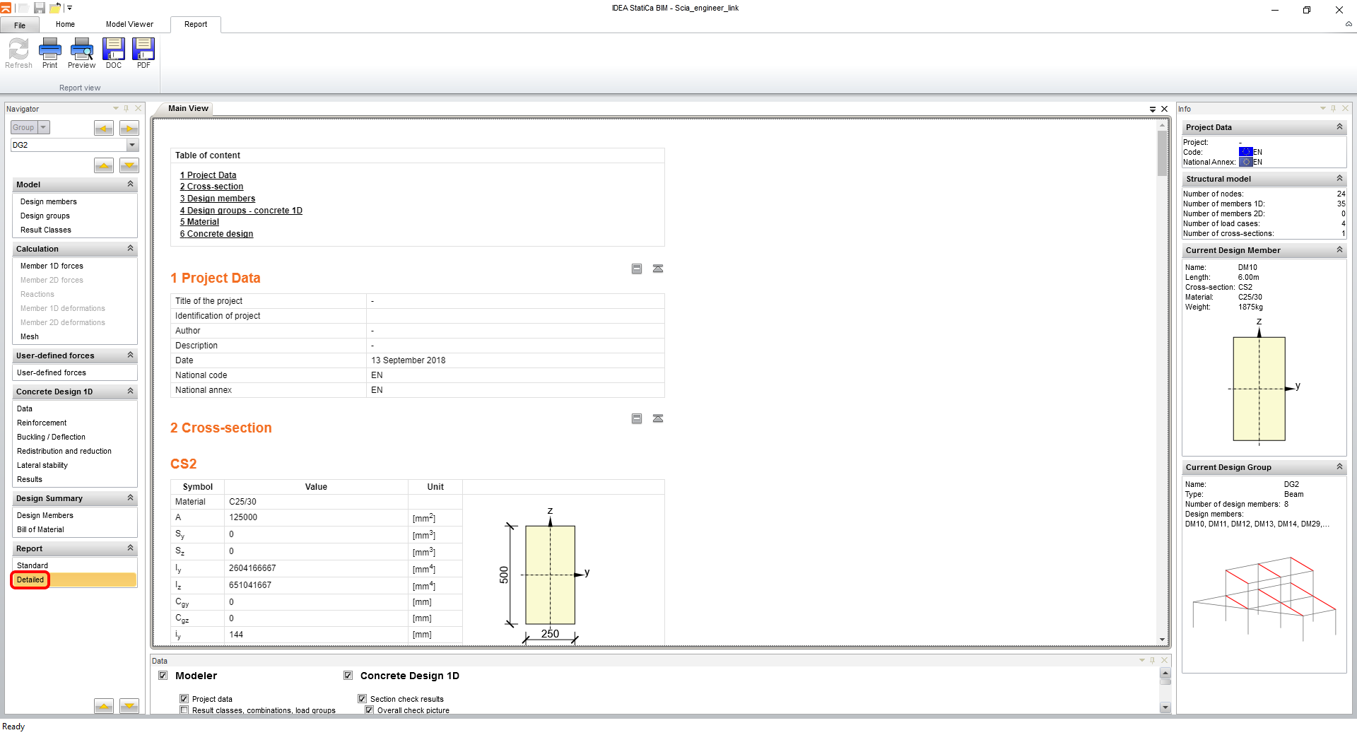
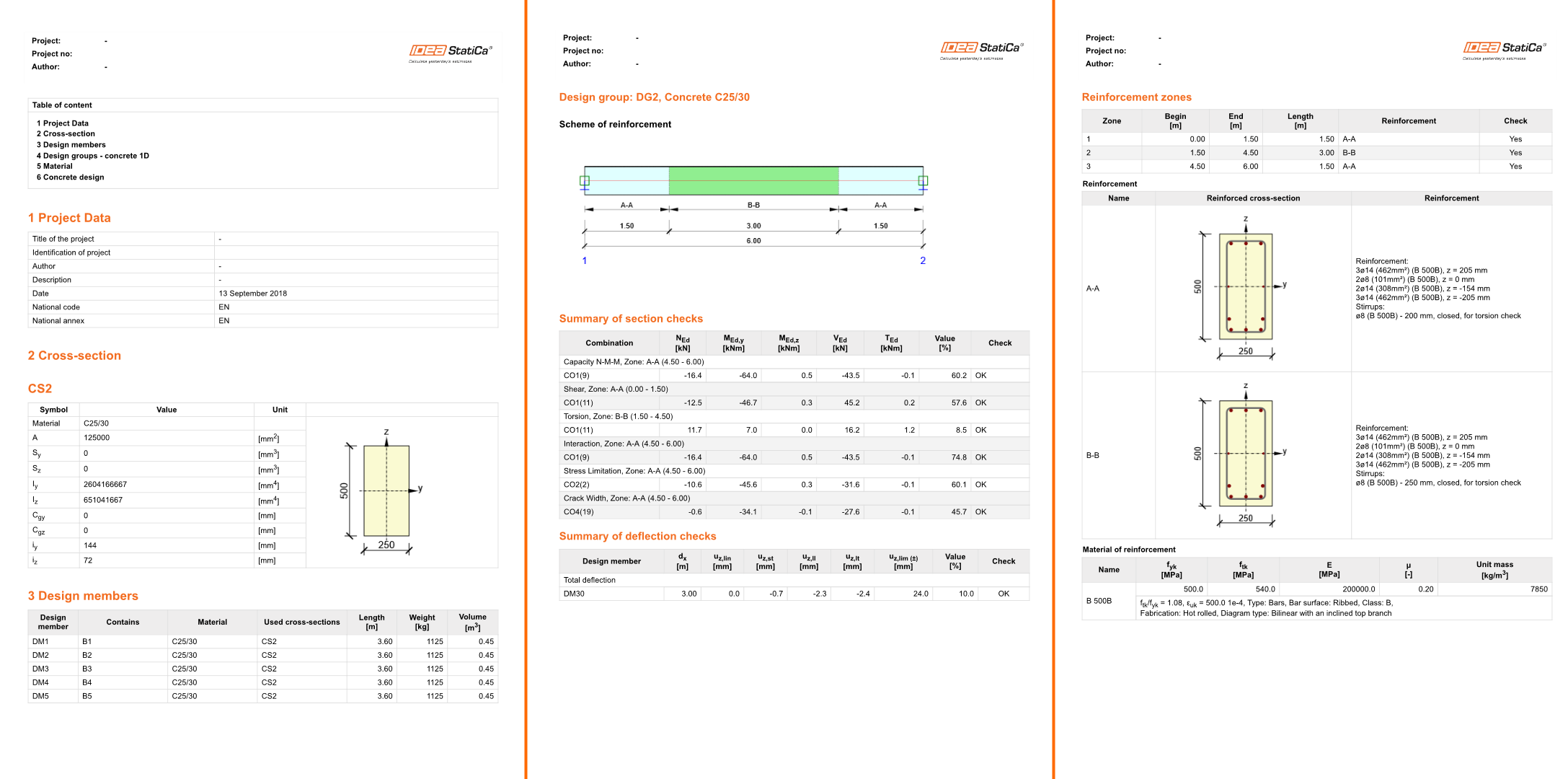
At last, you go to the Detailed tab in Report section in the navigator. IDEA StatiCa offers a fully customizable report to print out or save in an editable format.
7 Export of a part of a model (optional)
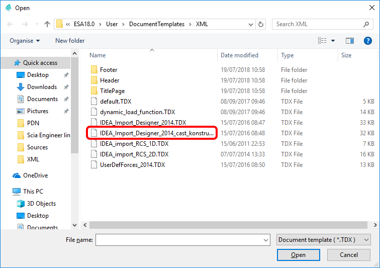
To export just a part of your Scia Engineer model, it is necessary to use a template called IDEA_Import_Designer_2014_cast_konstrukce.TDX.
Select it from the list.
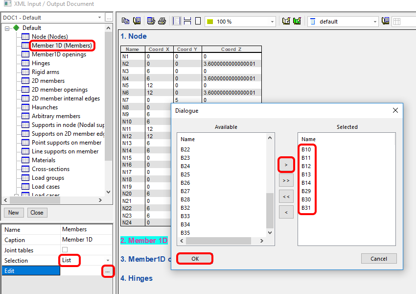
Select desired members for export in the XML entities tree.
The same selection is made for Internal forces to export.
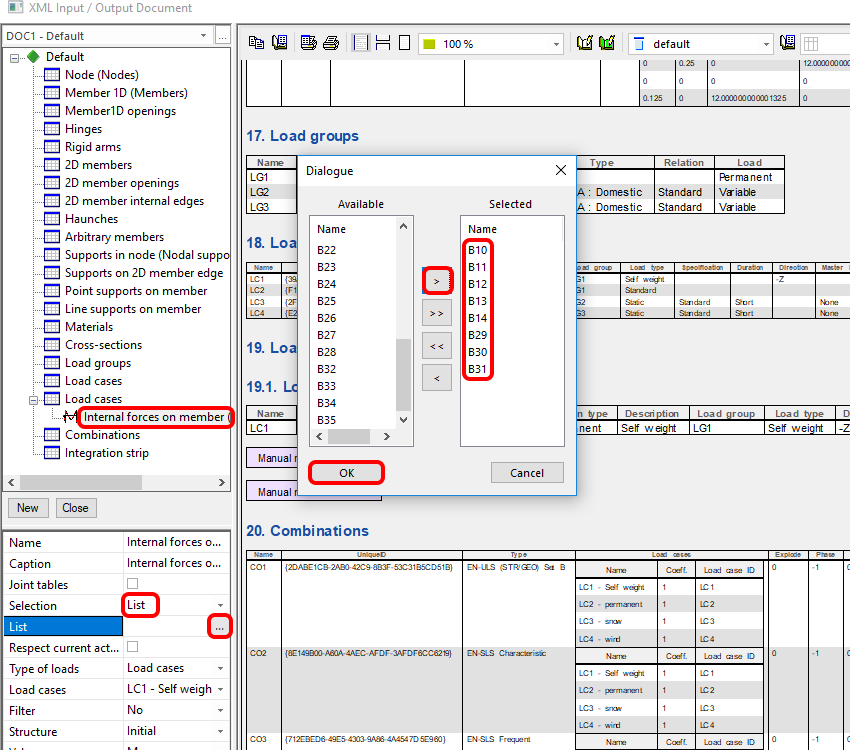
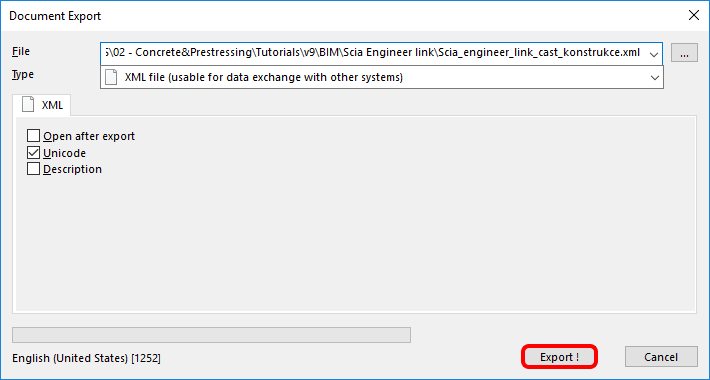
As in all the templates, click on Export.

Set the path for exported files and their name.
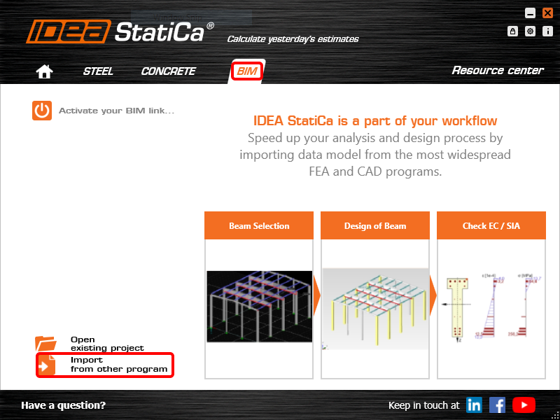
Open IDEA StatiCa and navigate to the panel BIM and click on Scia Engineer. Select the exported XML file.
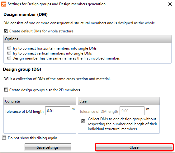
If you import for the first time, you need to set the generation of design groups and members.
The imported model looks like on the following picture.
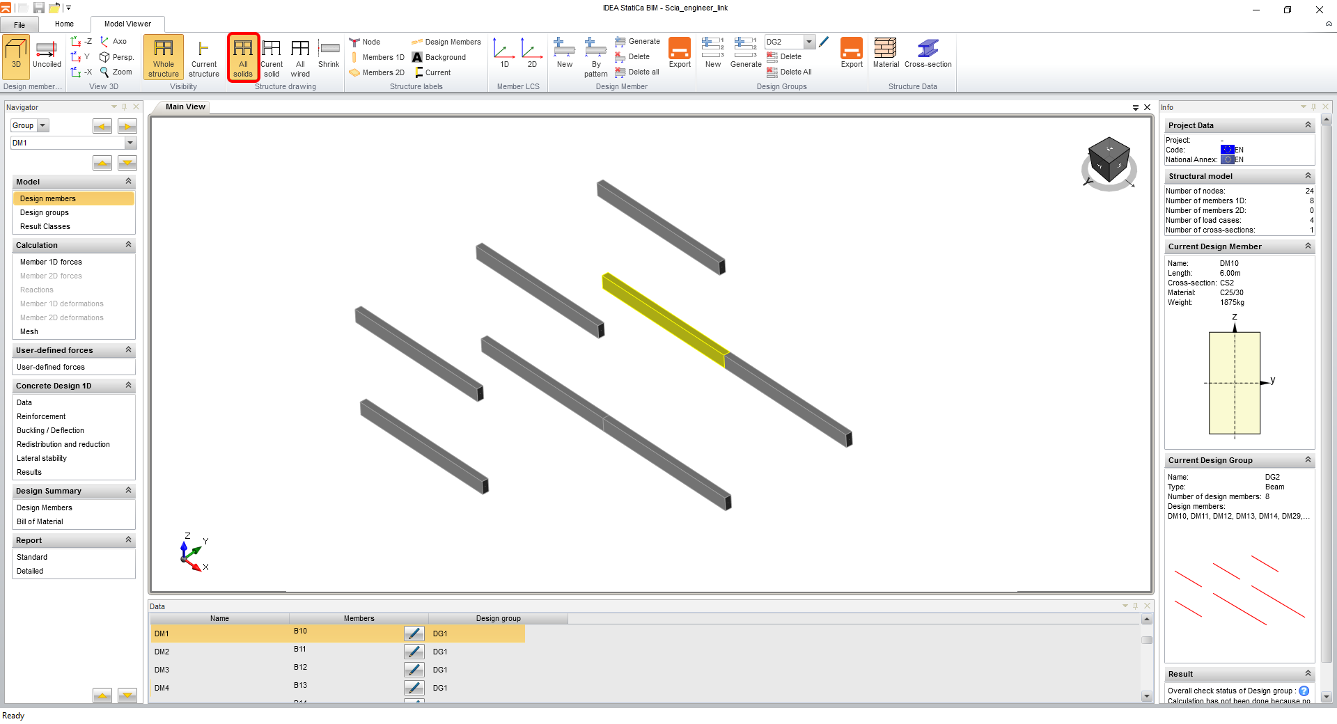
You can continue with exactly the same steps from section 4 Design.
8 Explanation of alternative TDX templates
The installed package contains several templates that can be used for different types of jobs even though the export process is the same. This chapter summarizes their use.
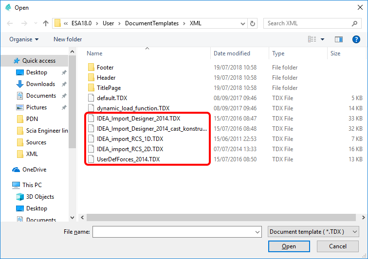
• IDEA_Import_Designer_2014.TDX
• IDEA_Import_Designer_2014_cast_konstrukce.TDX
• IDEA_import_RCS_1D.TDX
• IDEA_import_RCS_2D.TDX
• UserDefForces_2014.TDX
IDEA_Import_Designer_2014.TDX is a default template for the export of the whole model in Scia Engineer and is well described in the first chapters of this tutorial.
IDEA_Import_Designer_2014_cast_konstrukce.TDX is a template for the export of parts of the model in Scia Engineer and is well described in chapter 7 of this tutorial.
IDEA_import_RCS_1D.TDX is a template for the export of a section of 1D members for direct checks in the RCS application.
IDEA_import_RCS_2D.TDX is a template for the export of extremes on selected 2D members or global extremes of all selected 2D members for direct checks in the RCS application.
UserDefForces_2014.TDX is a template for the export of just the results of internal forces (e.g. moving load). The usage of this template can be seen in the tutorial for BLR in the Beam application.
Sample files
Scia Design Forms Tools Pack
Source: https://www.ideastatica.com/support-center/scia-engineer-bim-link-for-concrete-design-en
Posted by: lynchsweend1940.blogspot.com

0 Response to "Scia Design Forms Tools Pack"
Post a Comment